This project has been broken into 3 parts,
Part 1 - The Frame
Part 2 - The Electronics
Part 3 - The Code
This is part 1. Look for parts 2 and 3 coming soon.
Why would I ever build one of these things?!
It's funny, I actually don't care much to own a Segway-like robot and I only have a slight interest in driving one around. But for some reason I've been persistently wanting to build one! It feels very similar to building tree forts when I was a kid growing up in rural Idaho. I didn't particularly need a fort for any nefarious pre-teenage activities or want one for anything in particular, but there was a certain euphoria in building and creating and problem solving that apparently I still carry with me today. There's also something uniquely ego empowering about creating something all by yourself that only a few other people in the world (or a few hundred people in this case) have succeeded in building. A few years ago a friend and I made a pulse-jet engine in the machine shop of our college from plans we scrounged up off the internet somewhere. We were so proud to know that we had made something that only the WWII National Socialist German Worker's Party and a few other weirdos had ever made. What made it even better is that about a year ago I was eating lunch at work and a coworker mentioned a home built pulse jet engine that he had built and tinkered around with. It turns out that these curious projects of randomness are not just good for setting yourself apart in a crowd, but also help to identify the other crackpots in the crowd that you should go introduce yourself to.
So far this project has provided me with a more consistent influx of gratification than I've experienced in several years. It's hijacked my grey matter to the point that by this time the wife knows when I zone out mid-conversation it's because my mind is churning on the next piece of the Segway puzzle, and coworkers are well aware that, like it or not, no lunch conversation will be absent of an update of how the build is going. I'm only half way through at this point so here's hoping the euphoria holds out and that I manage to make it into the circle of the few hundred geek elite...
Part 1 - The Frame
Parts List
| Quantity |
Item |
Cost |
Where'd I get it? |
| 10' |
1" square tubing 0.060 wall thickness (~1/16") |
$4.48 | Patton's Steel (SoCal and online steel supplier) |
| 6" |
1 1/4" square tubing, 0.120 wall thickness |
~$2 | Patton's Steel |
| 18" |
1" round tubing |
~$2 | Patton's Steel |
| 6" x 24" |
16 gauge (~1/16") steel plate |
$6.59 |
Lowe's (part # 69921) |
| 4' |
Flat metal bar (1/8" x 3/4" x 4') |
$5.58 |
Lowe's (part # 69723) |
| 3" |
Torsional spring |
$0.00 |
From a broken garage door torsion spring. |
| 1 |
Carriage Bolt (1/2" x 12") |
$2.50 |
Lowe's (part # 61928) |
| 1 |
Nut (1/2" x 13) |
$0.20 |
Lowe's (part # 63304) |
| 1 |
Stop nut (1/2" x 13) |
$0.24 |
Lowe's (part # 63406) |
| 2 |
Flat washers (1/2") |
$0.40 |
Lowe's (part # 63309) |
| 2 |
1/4" x 1 1/2" hex bolts |
$0.34 |
Lowe's (part # 63312) |
| 2 |
1/4" x 20 Stop nuts |
$0.24 |
Lowe's (part # 63403) |
| 2 |
Springs (13/16" x 4" x .120") |
$3.67 |
Lowe's (part # 246624) |
| 4 |
Flat washers (5/16") |
$0.48 |
Lowe's (part # 63307) |
| 3 |
#10-32 1 1/2" flat head screws |
$1.59 |
Lowe's (part # 550588) |
| 3 |
#6-32 1/2" oval head screws |
$1.98 |
Lowe's (part # 394555) |
| 2 |
Electric Wheelchair Motors |
$35.00 |
Pulled from an old used wheelchair I bought off Craigslist.org |
| 1 |
Can Spray Paint |
$3.98 |
Lowe's (part # 121993) |
|
Total Frame Cost: |
$71.27 |
|
Nice to Have Parts List (things you'll need eventually but really help to have at this point)
| Quantity |
Item |
Cost |
Where'd I get it? |
| 1 |
Potentiometer (you'll need 3 in total) |
$0.50 | Tayda Electronics (part #A-1961) |
| 1 |
Potentiometer knob (you'll need 3 in total) |
$0.22 | Tayda Electronics (any of these) |
| 2 |
12v 12AH sealed lead acid (SLA) batteries |
$47.98 | Amazon (these were the cheapest) |
|
Nice to Have Parts Total | $48.70 |
|
Tools List
Welding helmet (I bought the auto-darkening version for a few bucks more, it's awesome!)
Let's Get Started!
I got some initial details on building a self-balancing robot (or 'bot' for short) from
John-David Warren's project documented in chapter 11 of
Arduino Robotics which is a great resource for the build and is where I plan on getting the basis of the arduino code. The book gives some good electronics and sensor and arduino basics and has some other great projects like a Roomba-like robotic lawnmower, an autopiloted boat that follows waypoints and a battle-bot to name a few (you can see a smattering of these on his
website but it looks like all the juicy details are hidden away in the book). I deviated from JD's design in a couple places, namely his design turns with a potentiometer that the rider turns by hand. I wanted the steering to be more intuitive so that's where I started my design.
In order to turn I want to simply lean the T-bar (ie. handlebars) to the right to turn right or left to turn left. That way you can keep both hands at 10 and 2 (uh... or -1 and 1 I guess in this case) and no fiddling with knobs. I knew I'd need a torsional spring in order to allow the handlebars to pivot and to keep them off the ground when someone wasn't riding it. Luckily, I recently replaced two 4 foot torsional springs on my garage door a while back and had kept them since you never know when you might need two 4 foot torsional spring, right?! I also wanted to make the T-bar easy to swap out so that I could put a shorter one on for my boys who may get the courage to step onto one of daddy's contraptions someday (with appropriate safety gear and adequate adult supervision of course).
What you see below is the main steering mechanism. I forgot to take pictures of it pre-weld so this will just have to do.
The larger tubing is 1 1/4" square tubing with a 0.120" wall thickness which fits the 1" square tubing inside with a little slop. I get the slop out using bolts shown in pictures farther down in this post.
I should explain that I don't normally call what I do 'welding', I normally call it 'sticking metal together for a temporary amount of time' but that's too long and noone knows what I'm saying when I try to use SMTFATAT as an acronym... it'll catch on eventually.
You can see how if you torqued the larger tubing (the short piece) to the right or left and let go, the torsional spring would spring it back into place. The sleeve piece that goes over the spring will be welded (or SMTFATATed for those paying attention) to the frame later as well as the long piece of smaller tubing. This should reduce torque on the steering mechanism as the rider jerks the T-bar forward and backwards and prevent the cantilevering that would break my so-called welds (keep reading if that didn't make sense... or even if it did).
At this point I had welded it all together and it was a little cock-eyed, meaning my T-bar would lean slightly to the right if I mounted it at this point. I'll remedy that later in the post.
Now that we've got a way for the T-bar to stay vertical I need to incorporate a sensor that will drive the steering. This is where the 12" carriage bolt comes in. The carriage bolt runs through that mechanism we just built and has a potentiometer hot glued into a locking nut at the end.
Here's a pic of the potentiometer in the locking nut pre-glue. We'll fix that potentiometer to the frame later in the post so that it can tell when the T-bar is being leaned left or right. In the meantime though we've got to get that carriage bolt through the mechanism and fix it so it turns with the T-bar portion (the shorter piece). First we drill...
Done! (I feel like I'm on a cooking show where I already have a finished casserole already waiting for me in the other oven...)
So at this point I could have gotten out the Dremel tool and cut that circle into a perfect square to fit the square peg at the top end of the carriage bolt, but to be honest I couldn't find my dremel tool so instead I drilled four smaller holes in a square pattern and just gave the carriage bolt a good whack with the hammer you see in the background to seat the bolt in place.
It ended up working really well. Unfortunately I forgot to snap a pic at this point so you'll just have to imagine it... or scroll down 13 photos and peek at some of the later photos that show it in place.
Cool. Now we put the steering mechanism aside and start building something to attach it to. The motors is probably the best place to start for this. This part will be a little different for every build depending on what motors you're able to get your hands on. Mine came from a very old electric wheelchair I found on Craigslist for $35. I hooked them up to a car battery and they seemed to work just fine so I was happy with the purchase. I had to mount the wheels (I used
these but you can use whatever) onto them myself which was a little work and some welding but hopefully you're able to find something strong and cheap and geared that already has wheels. Electric wheelchair motors seem to be the favorite for most Segway builds, check ebay or your local Craigslist for options. I did have to remove the electro-magnetic brake from each motor when I got them and you'll most likely want to do the same. These prevent an electric wheelchair from rolling down hills in case the batteries ever fail on an incline, but on your Segway they'll just be sucking up a bunch of power holding a brake open anytime you want to move. There are several
youtube videos on how to remove these brakes but can post pics on the procedure I performed if people would like me to.
To start I cut motor mount plates out of some 16 gauge steel (~1/16") plate.
I then measured out the motor mount hole pattern and drilled the mounting holes. It took a little work to get all the holes to line up just right.

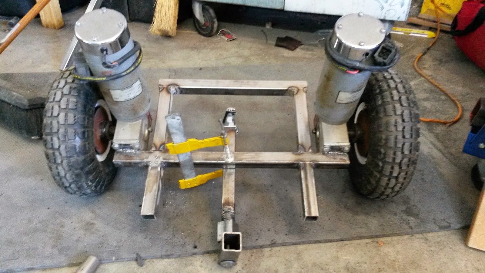
With the motor mount plates attached to the motors, I removed the wheels and set both motors on a level surface to ensure that when I welded (SMTFATATed) them together they would be reasonably straight and parallel. It's around this time that you have to decide how you you want your motors oriented. I ended up standing the cylindrical motors up straight even though it sacrificed some of my standing platform real estate. Other builds put them either pointing out the front or out the back (e.g. JD's point out the
front while a close copy of JD's build points them out the
back). However you choose to do it you need to consider ground clearance (i.e. will the motors scrape the ground if you lean too far forward or backwards) and try to keep a low center of gravity. A low center of gravity will make the vehicle more naturally stable so the robot won't have to work as hard to maintain stability (stay upright) with you on it.
Look at those sexy welds (SMTFATATs)! Go ahead, blow it up full screen and drool over those metallurgical beauties. Just be careful not to make the wife jealous.
I used an 18" piece of tubing between the mounts which won't allow me to have a overly wide stance on the Segway but should keep the frame narrow enough to fit through most door frames.
Now that the motor mounts are connected it's time to start piecing together the standing platform. And yes, I realize putting my 18lb Segway frame on 3 ton jack stands is ridiculous but those things actually proved to be quite useful since the frame just wants to roll around without them.
I wanted to keep the rider standing roughly over the wheel axles since that should make it easier to maneuver. This is a picture after adding 4 1/4 inches of tubing out the front. I cut most of my metal with a cheap angle grinder but a compound miter saw with a cutting disc would have made it easier. Use it if you got it. I also only welded on the vertical sides (two sides) and could have also welded the bottom (3 sides), but I was trying to keep the joint on top without a weld since eventually a piece of metal or wood will be laid on top as the standing platform and I wanted to keep the top as flush as possible.

The is Pete, my 6 year old, who performed his first weld (SMTFATAT) with me during the build. I don't think he'll be picked up to manufacture aircraft carriers anytime soon but you got to start somewhere! It's also important that us eccentrics pass our traditions and cultures onto our kids. Otherwise in a few generations the world could be completely devoid of strange and random people, and noone wants that right!? ...right?

This is a pic after adding 6 1/4 inch tubing sections out the back and a cross piece connecting the two (cross pieces were about 13 inches). In order to decide the dimensions of the platform I just kept standing or mock standing on the slowly forming platform to see how much room I would need. I also looked up the dimensions of the batteries I'd be using since I planned on mounting those underneath the platform. The batteries really determined the dimensions of this back part of the platform. You can see the steering mechanism clamped into place in the pictures above and below as I was continually fit testing things to make sure the plans in my head would work in reality.
Another picture of the test mount of the steering mechanism.
With the front cross member welded on and some dimensions for reference.
So now we come back to the steering mechanism we already built. Here it is mounted in place, ready to be welded.
Another pic pre-weld. This set of welds are kind of important ones since I don't really want to make another steering mechanism piece. I think I could overlook being off by 1/8" anywhere else on the frame but I think it would really nag at me if the steering was a little off kilter.
So, I made sure to measure everything fairly precisely and mark the midpoints of both piece to be welded so I could line them up. you can see the midpoint markings above... and below.
Another midpoint marking to make sure I had everything lined up before welding. This helped since sometimes things shift as you're getting everything setup to weld. I could tell if they were still lined up at a glance with the markings. I could have done precise measurements and marked everything up for the whole frame like I did for this piece but didn't think it necessary.
And here it is post-weld. Looking good, eh?! I only put three welds down to attach the steering mechanism since I couldn't fit the welding tip between where the Tbar will mount and where the farthest forward weld would be. I could have tried but it would have been ugly. I'm not too worried though, it feels pretty solid as is.
Now onto building the Tbar!
You've probably been thinking, 'What the heck is this Tbar this kid keeps mentioning?!' The Tbar is just the T-shaped handle that you hold onto and use to lean forward and backward and lean right and left to turn/pivot (see four pictures down since a picture's worth a thousand words and I've already wasted 57 of them).
This was a pretty simple portion of the frame to build since it's just a long square tube with a round tube welded on top. However, attaching those two nicely took a little work. I used the round tubing to trace out the part I wanted removed from the top of the square tubing and then used the angle grinder to kinda wedge it out of there.
Like so. I could have just cut a 'V' shape and placed the round tube in the 'V'... like this,
...but I was trying to make it pretty.
I used 90
° angle magnets to keep it squared up until I could spot weld it in place. Again, I feel like it would just bug me if I was constantly driving around with the handle a little bit tilted so I was trying extra hard to keep things square. When I welded on side I kept the 90° angle magnet on the other side in an attempt to keep it about right and it seems to have worked as far as I can tell.
Sweet! Now that the T-bar's done it's time to mount it in the receiving sleeve and get this thing looking like a legit Segway! That way friends and family will stop referring it to as "that metal thing with wheels in your garage".
I put the T-bar in the sleeve and used a 1/4" drill bit to drill through the sleeve and the bottom of the T-bar. The pic only shows one hole but I put one at the top and one at the bottom of the T-bar receiving sleeve going through both the sleeve and the T-bar with both holes. I used the screwdriver in the photo above to keep the Tbar pushed up against the front of the sleeve, this was intended to minimize the wiggle room or slop in the T-bar mount. I'll be pushing and pulling and twisting the T-bar with quite a bit of torque if all goes well and I don't want there to be a lot of play that would result in a dead-band between pushing and pulling (dead-band meaning you can't go from push straight to pull, you'd have to stop pushing, rotate through some small angle, and then you'd metal on metal again allowing you to push).
Now there's a Segway frame people will respect! You can stand proud next to that stunning piece of work.
At this point I confirmed a suspicion that I had had after attaching the steering mechanism to the frame, the torsional spring was not strong enough to hold up the T-bar by itself. Also, then I welded up the steering mechanism the T-bar sleeve ended up not being straight up and down anyways. These problems were easily remedied with two springs and four 5/16" washers from Lowe's (see the parts list for product #s).
I started by welding two of the washers to the back, outside portions of the T-bar sleeve with the entire washer opening poking over the side of the sleeve (open the pic in a new tab and zoom in if needed). I welded them to the sleeve instead of the T-bar because I wanted to keep the flexibility of swapping out to a short T-bar for my kids or modifying the T-bar used by adults if I thought it was too tall... which I suspect it might be just from preliminary imaginary test runs.
In order to attach the springs I leaned the T-bar all the way to one side with the spring already in the welded washer and clamped the not-yet-welded washer (already attached to the spring) down using vice grips (see pic) as close to the edge as I thought reasonable. With this clamped in place I was able to weld it with relative ease since I didn't have to hold anything down or be fighting the spring tension.
To attach the last washer I leaned the T-bar all the way over, tightening the already attached spring, and clamped the washer close to where I thought it should be with vice grips. I then brought the T-bar back up straight to see if it could remain vertical by itself. A magnetic bubble level came in handy for this part which you can see in the pic above. I fiddled with it until it was finally perfectly vertical by itself and welded the last washer in place.
Voilà! Effective. Out of the way. And most importantly, shiny.
With that done I moved onto the battery boxes. The batteries are heavy and I tried to place them so that the frame was pretty well balanced before we started trying to actively balance it with sensors and motors and controllers. I was initially going to use 12v 10AH batteries since they would leave plenty of ground clearance but the 12AH ones were just $2 more and I couldn't resist getting the extra mile or so of range for that price. Whatever you use make sure that you know the dimensions ahead of time, it helps to have them on hand but you can usually trust the dimensions provided by Amazon or other websites.
With 4' of flat metal bar I had just enough to build the two battery boxes. You want the batteries to sit low enough that they'll fit nicely under whatever you use as a platform to stand on but at the same time you want to give yourself as much ground clearance as possible so they're not scraping on the ground.
With this information I measured how wide and how tall my boxes needed to be and marked the flat metal bar at the appropriate bend locations.
This is the part where the vice really comes in handy.
I first just bent it over by hand as shown above but that didn't give it a really crisp corner.
So I gave it a few good whacks with the hammer in the background and that did the trick.
Do it to the other side and you have yourself half a battery box.
When I had them all finished I lined them all up and made sure they were all the same height, I had to trim down one or two that were a little taller than the rest. I think we're all familiar with the old Chinese saying, "The tallest battery box hanger is the first to get cut with the angle grinder."... it goes something like that anyways.
Bend and squeeze until they seem to be about right. It's good to fit check with the real batteries at this point if you've got them. Then just weld, weld, weld. I only welded on the outside since it was a tight fit and didn't want a gloopy weld getting in the way.
And here that are all welded in place.
And another view.
Here's a fit check with the batteries in place. There's not much room for the platform plate but I can always throw some washers in-between if needed to make it sit a little taller.
From this angle you can see the slim 1 1/2" of clearance I left myself. Luckily it's right under the wheels (I mean, I planned it that way!), and I can lean it almost all the way back before scraping the battery boxes. I figure if I tip over that far I've got bigger problems. My only concern now is that it won't be enough clearance for some of the big potholes on the dirt road I live on. I'll let you know how it goes the first time I take it to get the mail.
Finally, the compartment in front will be used to house all the electronics (arduino, speed control, inertial measurement unit (IMU) that tells how you're leaning, etc.) I cut a piece of flat plate to fit and then cut notches so it could fit around the welds in the middle. I also rounded the corners so it would fit inside the welds in the corners.
Tacked it in place and there you have it. I might need to drill some breathing holes for the speed control so it doesn't overheat or if I want to keep any small pets in there but I'll deal with that when I get there... or when I purchase a small pet that for some reason I want to make sea sick.
At this point I was ready to paint the frame. I washed it down with Dawn soap and water since steel it usually covered in grease to prevent it from rusting. After washing and drying I spray painted it and hung it up to dry. Here it is after the paint job.
...nevermind, this is where I realized that I failed to take a picture of the frame post painting.
Apparently I also failed to realize that I hadn't made a standing platform before painting. I cut a 13 1/2" by 14" piece of sheet metal since I had a bunch left over but probably would have used something cheaper (probably wood) if I hadn't already had it lying around.
I cut out some notches that you see at the bottom to fit where the springs attach to the frame.
I also rounded the corners (see above with our guest model, Benji) since these motors have some mega-power behind them. I feel like a sharp corner with 700 watts of power behind it is a recipe for disaster... or at least stitches.
I secured it to the frame with some counter-sunk screws and nuts. I wanted to keep the platform flush to prevent tripping, hence the use of countersunk screws. The pic above is what I'd call 'poor-man's countersinking' which is just done with a larger drill bit than the original hole and some creative drilling.
Here they are in all in place and looking good. I'm looking for some skateboard grip tape to throw on the standing platform as well but I haven't found any yet and I'm not sure that I'll really need it.
Now I'll need to attach the potentiometer that we hot glued into the stop nut at the end of the steering mechanism. I cut a small piece of steel plate and drilled a hole for the potentiometer to fit through. You'll also need to drill another small hole for the peg that prevents the potentiometer from spinning (the little hole to the left of the shaft in the pic above).
Next, I attached the plate and potentiometer and stop nut to the carriage bolt as it will be when operating and used the standing platform plate to mark where the potentiometer plate should be bent. I did this by removing the platform plate and sliding it forward until it butted up against small potentiometer plate (see above). I marked where the two met and bent at the mark.
With it bent I drilled holes in the platform plate and potentiometer plate and attached the two using counter-sunk screws (#6-32 oval machine screws in the parts list) and nuts (I had some in a junk box that fit). The knob came unglued as I was working with this part so I'll have to re-glue it, maybe with epoxy this time.
Here it is in place before drilling the holes in both plates.
I drilled through the potentiometer plate and them lined it up on the underside of the platform plate and marked where the holes needed to be in the platform.
Here are the counter sunk holes in the top of the platform. Looking sexy!
Here's the platform after I spray painted it and hung it up to dry. I let the boys spray paint the underside so there's huge running streaks and half a can of spray paint on that side. I chose to show you the 'show side' of the platform.
And there it is! A completed Self-Balancing Ridable Robot Frame. Take a moment to step back and appreciate your accomplishment. Crack open a celebratory Dr. Pepper; call the wife and kids out to come admire your achievement with you; or, might I suggest, blog about it to perfectly random strangers. Whatever your moment of relaxation is, make it quick cause we've got some soldering to do!
On to Part 2, The Electronics!


.jpg)


